![]()

|
Datasheet |
|
| Name | MR1 |
| Size | 97mm x 96mm x 94mm (length x width x height) |
| Weight | 360g without batteries 490g with batteries |
| Power supply | 1 x 9V battery for electronics 4 x1.5V R6 / AA for motors |
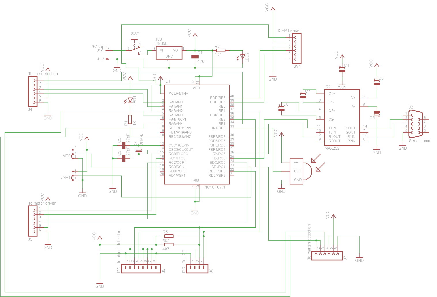
| Microcontroller | PIC16LF877A - I/P @ 20MHz, 5V |
| Motors | 2 x GM9 (the original motors have been replaced by RM2) |
| Motor driver | 2 x L293D , 1 for each motor |
| Wheels | 2 x GMPW-9, 67mm diameter |
| Tires | 2 x GMTT, 71mm diameter |
| Opponent detection sensors | custom board based on PIC16F88 and 4 x IR LED + 4 x TSOP1738 receivers |
| Margin detection sensors | 2 x RPR-220 ROHM |
| Line detection sensors (in line follower mode) | 3 x RPR-220 ROHM |
| Pushing strength | tested on a 1600g box with paint |
| Communication with PC | RS232 serial communication @57600baud |
| Operating modes | remote controlled mode diagnose mode autonomous mode, executing the selected program |
| Executed programs | auto-calibration program minisumo defensive program minisumo offensive program line follower program |
| Microcontroller software | The software is written in C
language for Hi-Tech PICC compiler You can download it from here. |
| Schematics of the control board | You can see it here. |
| Schematics of the opponent detection sensor board | You can see it here. In the schematics thare's a mistake: pins 5 and 14 of PIC are wrong connected to Vcc and GND. |
Construction details
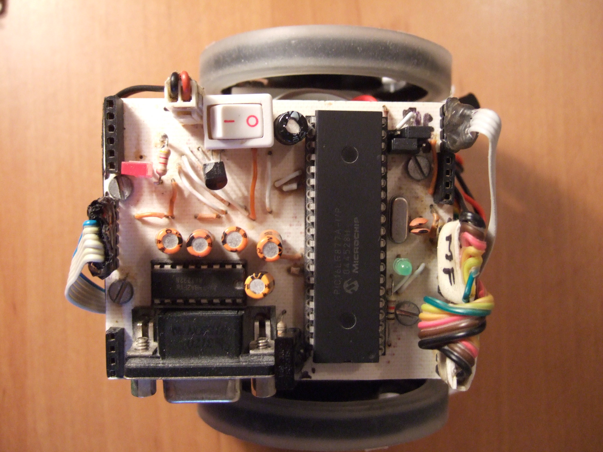 |
Upside view
1 = PIC16F877A microcontroller |
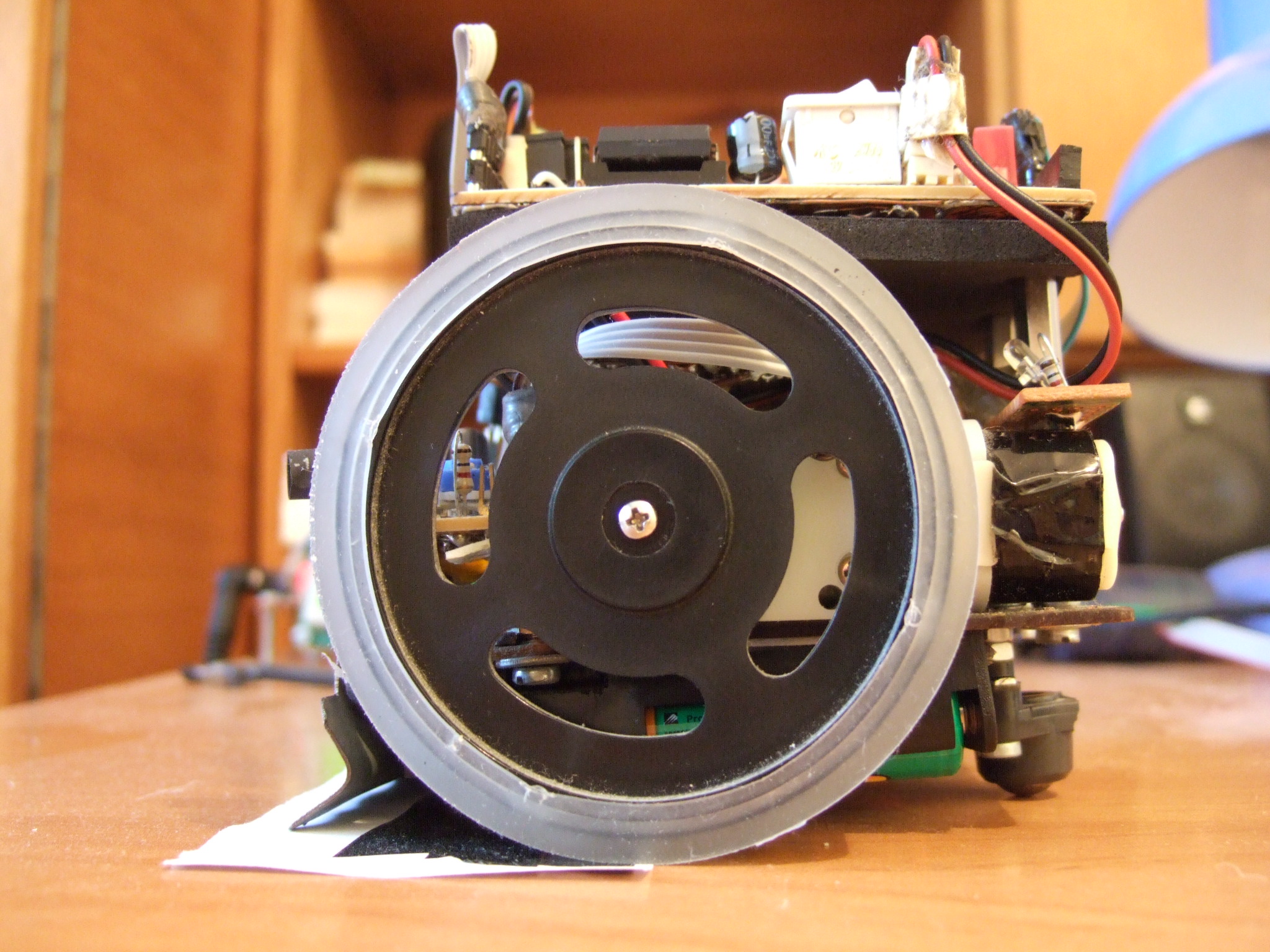 |
Left side
view 1 = left motor |
 |
Right side
view 1 = right motor |
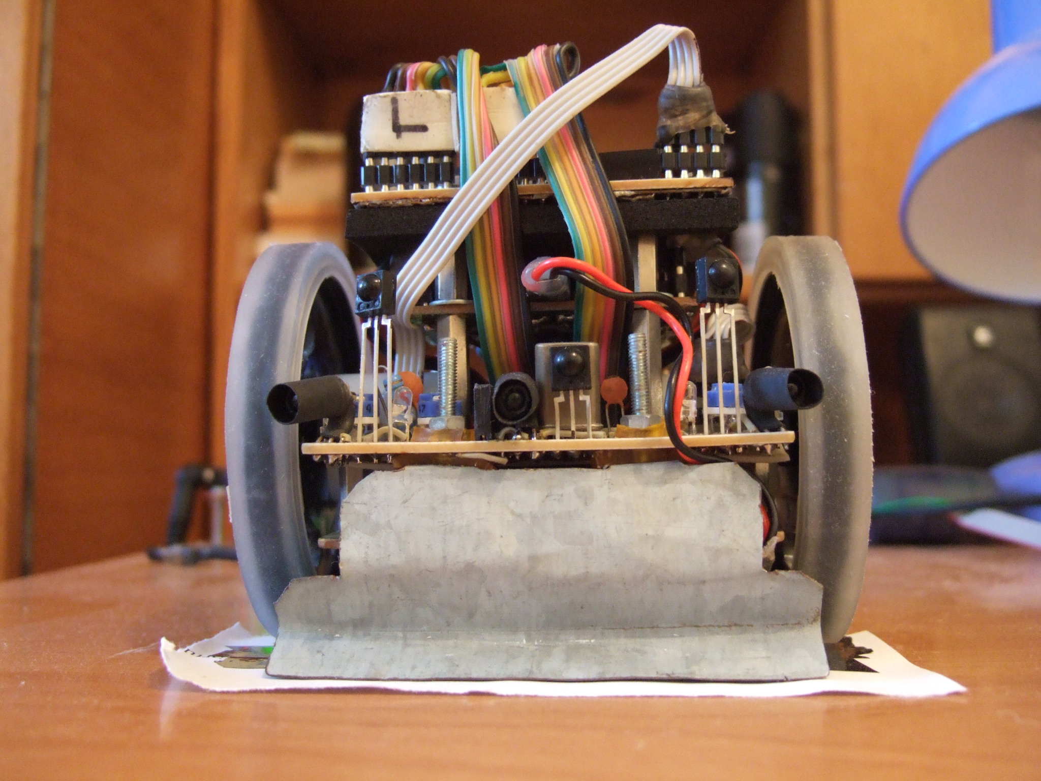 |
Front side
view 1 = IR LEDs which send 38kHz
beam for opponent detection |
 |
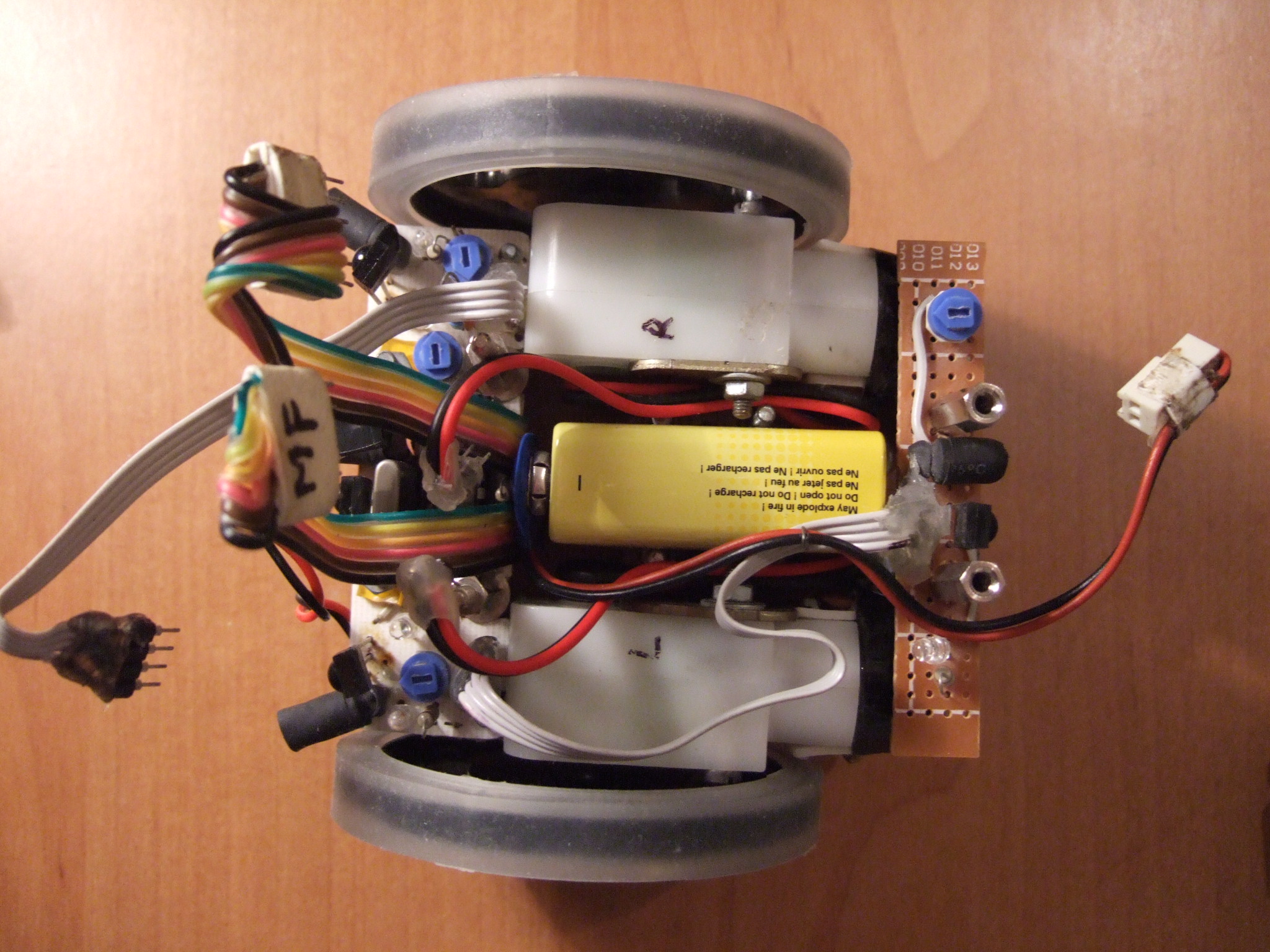
Rear side
view 1 = 9V battery to supply the
electronics |
 |
Downside
view 1 = 1.5V batteries |
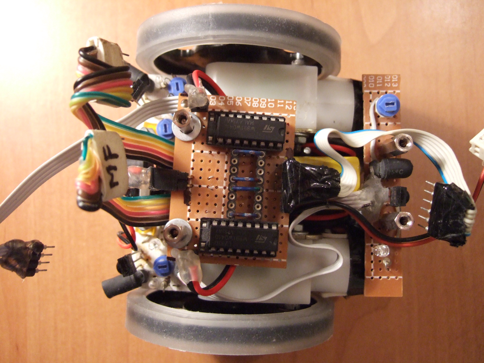 |
Upside view
with mainboard removed 1 = L293D
motors driver |
 |
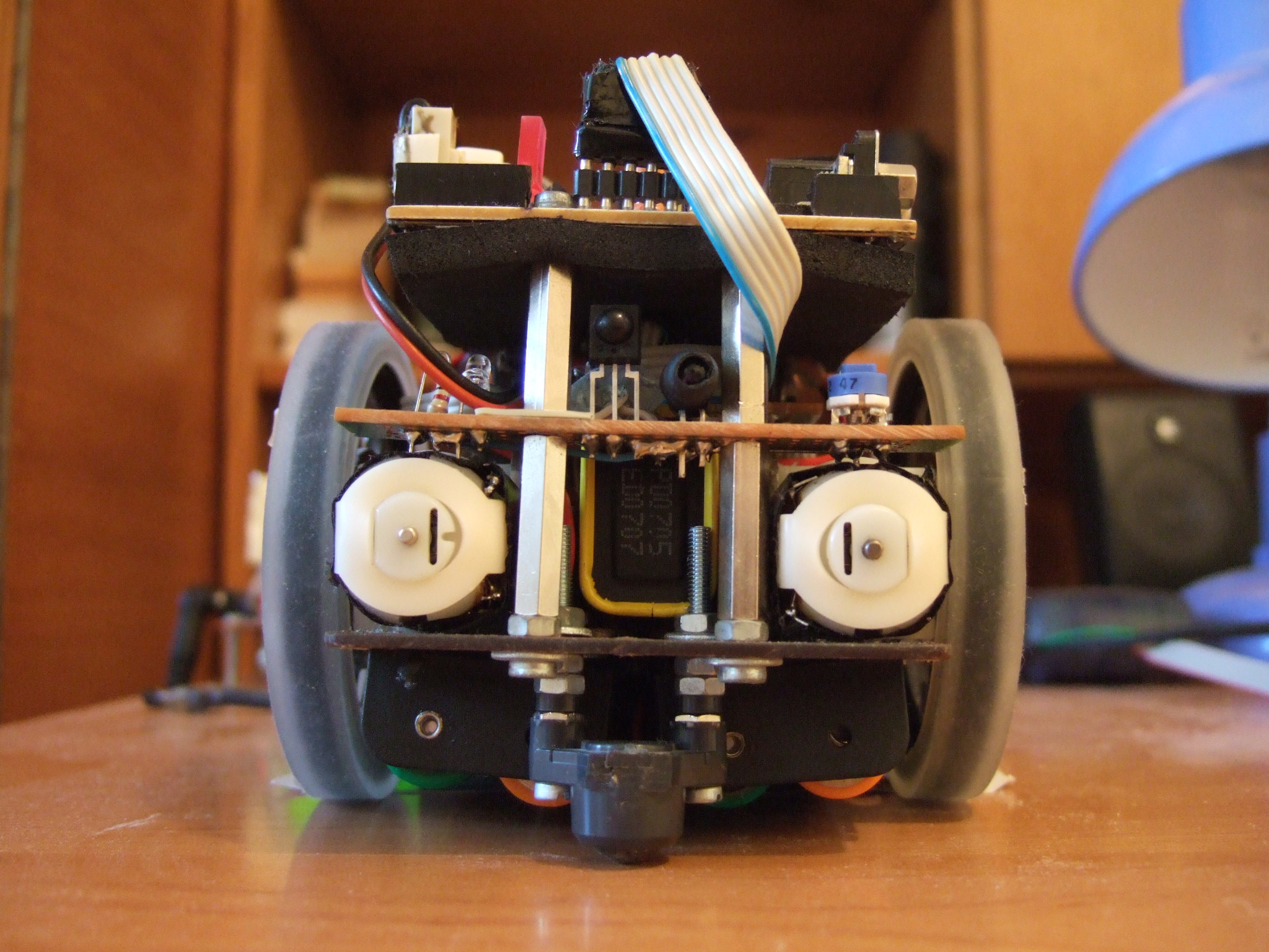
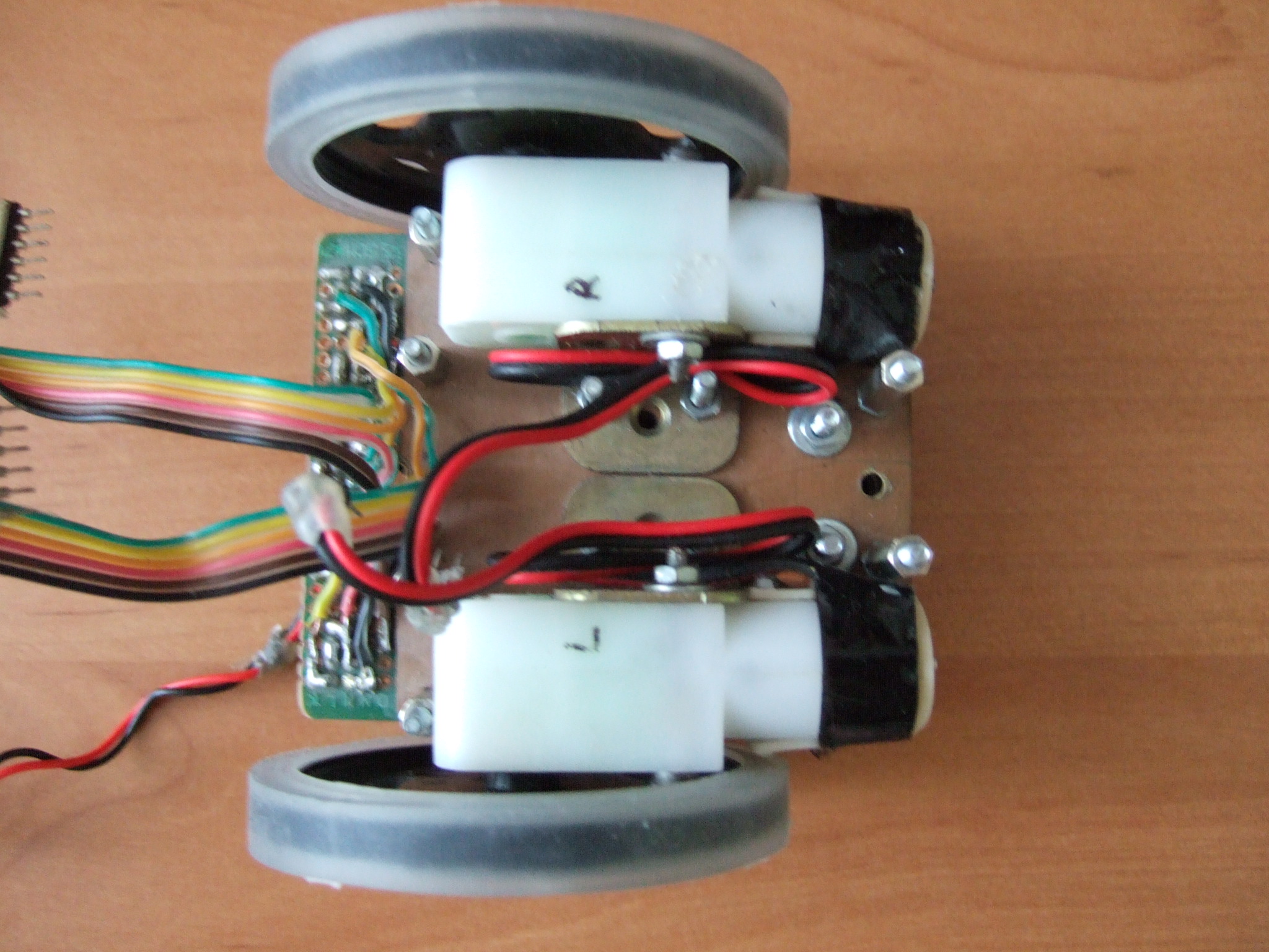
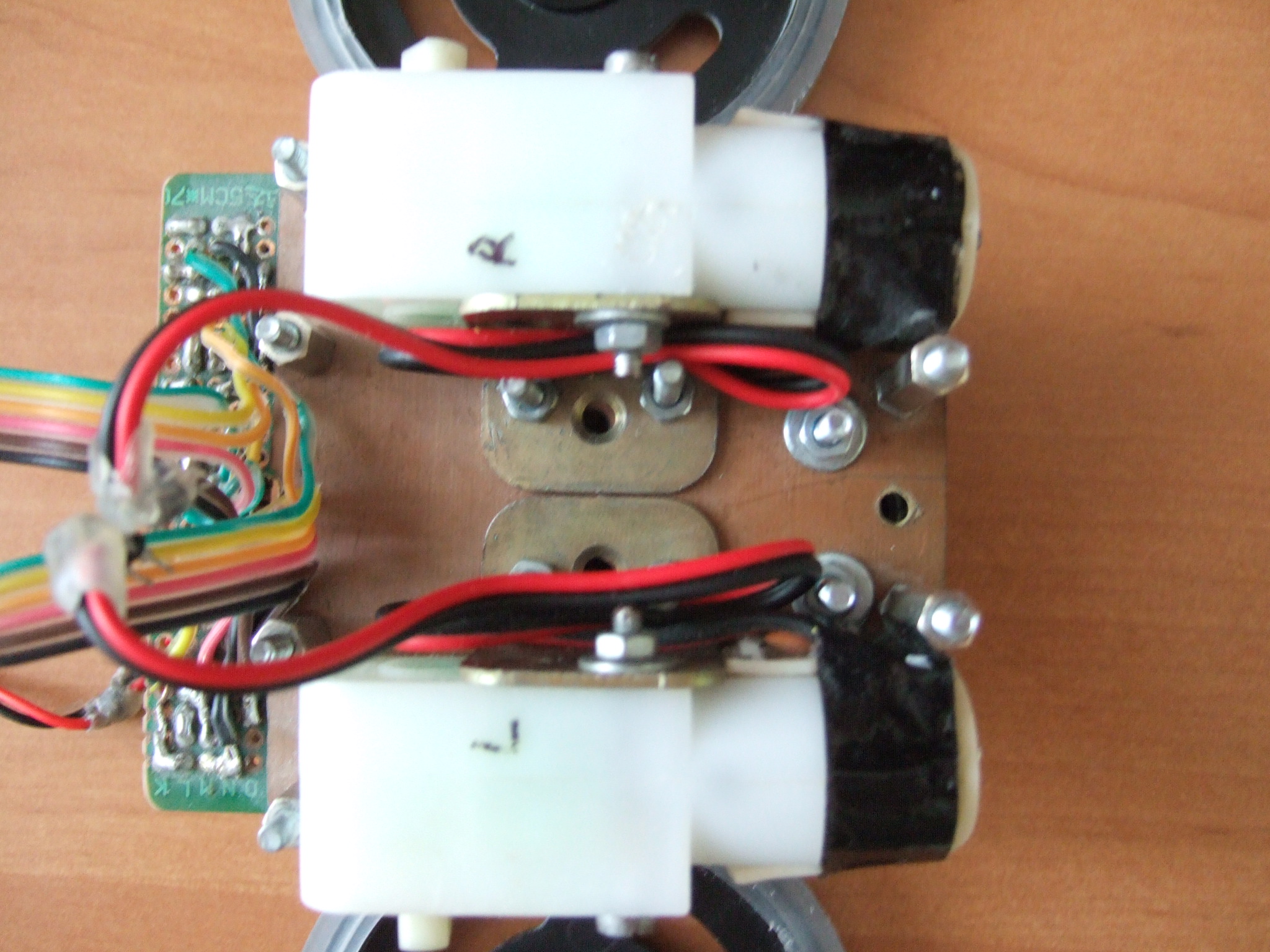
Upside view
with motors driver removed 1 =
gearmotors |
  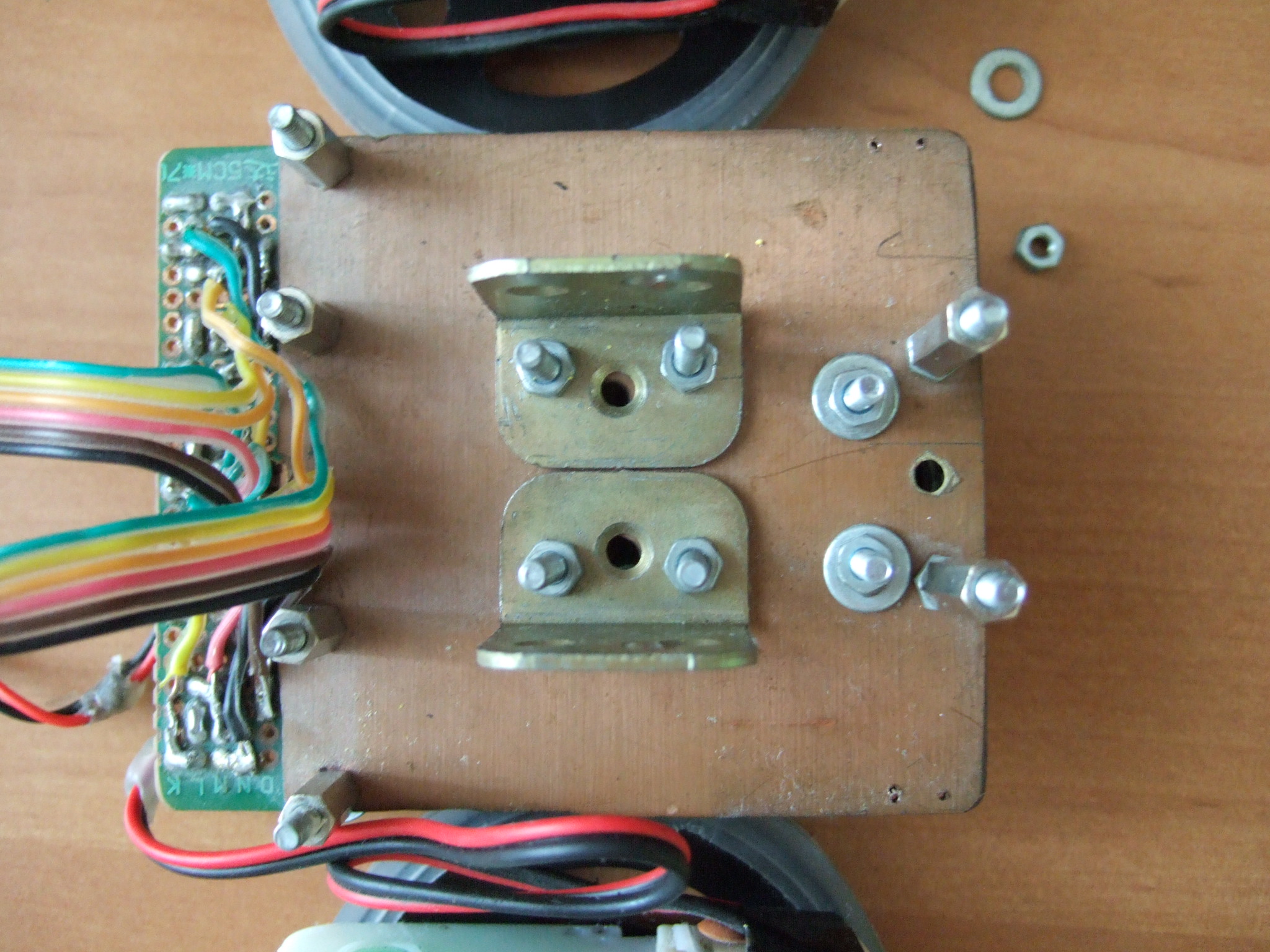  |
Chassis - details |
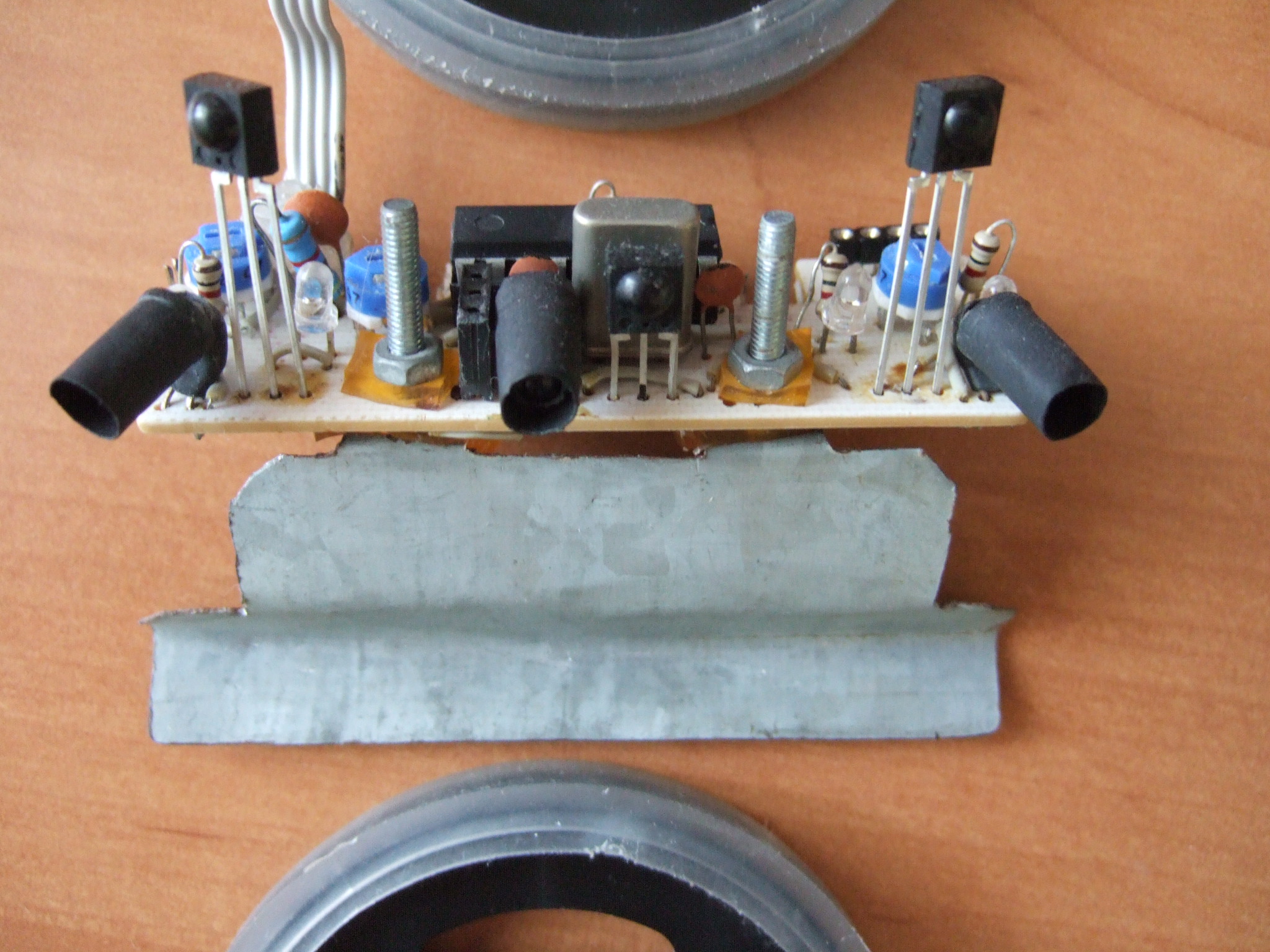 |
Opponent
detection sensor and front scoop - details The opponent detection periodically sends 5 modulated pulses with a duration of approx. 600us. Each pulse is followed by a 600us break. This is happening consecutively on all of the 4 emitting LEDs ( 3 in front side and 1 in the rear side). In the same time with the emission of these pulses, the reflections received by TSOP1738 are counted (using interrupts). If at least 3 reflections are counted, MR1 decides that there's an object in the direction of the corresponding emitter LED. By construction, I surrounded each LED with a heat-sink dark tube, so it can't emit its beam directly in the direction of a TSOP receiver. In this way, ideally, the TSOPs "catch" only the reflections. |
 |
Functional
architecture diagram The LCD with I2C interface is not a part of the robot, because it would make it heavier than 500g. It can be added for debug purposes. |
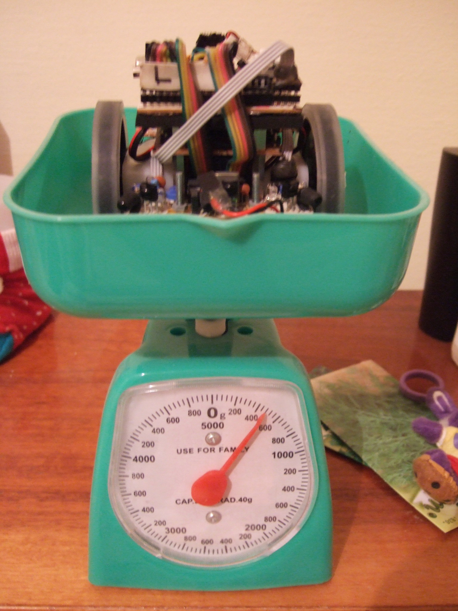 |
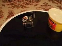
Weighing test |
|
|
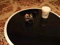
MR1 pushes
650g In this short movie, MR1 must push a white box with paint out of the ring. The box is weighing approx. 650g. |
|
|
MR1 pushes
1600g In this short movie, MR1 must push a white box with paint out of the ring. The box is weighing approx. 1600g. |
|
|
MR1 against
photo camera In this short movie, MR1 is pushing out of the ring the photo camera. |
Functional description
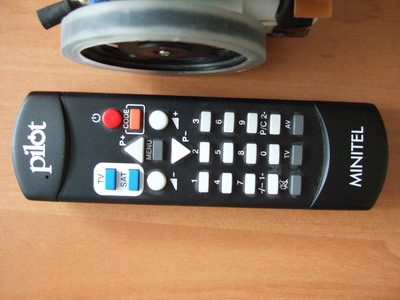
Remote controlled mode
This is the functional mode with the highest priority. When MR1 receives a valid code from the remote TV control, it executes the associated command immediately, regardless what it was doing in that moment. MR1 enters this mode immediately after receiving any valid code and it exits the remote controlled mode only when the OFF key of the remote TV control is pressed.
Diagnose mode
MR1 enters in diagnose mode immediately after receiving a diagnose command and exits automatically this mode after 5 seconds has ellapsed without receiving any diagnose command. MR1 receives diagnosis commands via serial link from a diagnosis software running on the PC machine. Each diagnosis command it’s made by a request ( from PC to MR1) and a response (from MR1 to PC) like below:
MR1 receives the request from PC ---> MR1 executes the action asked by the request ---> MR1 sends the response to the PC
The diagnosis software on the PC machine, sends simple diagnosis commands to MR1: robot movement control, motors rotation control ( speed, direction), reading sensors, calibration of sensors. These commands are very useful when I want to test the functionality of the rob
For example, it happens some times to make a major modification in the software and after “burning” the hex file, I see that the minisumo robot does not move anymore. In such a situation, the first question is: “is any motor or sensor crashed or I have just another software bug?” This question can get a quick answer using the diagnosis!

Autonomous mode
This is the mode in which the minisumo robot is the most part of the time. MR1 enters this mode immediately after switching on and every time it exits any of the previous modes. In this mode, the robot executes the program selected by the program selection jumpers.
Executed programs
My minisumo robot can execute 4 different programs. These programs are selected via the program selection jumpers.
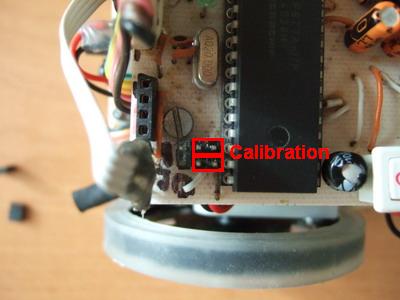


Self calibration program
The purpose of this program is to calibrate the tresholds between “black” and “white”, for the line and margin detection sensors. Also, it decides the duty cycle of the 38kHz beam emitted by the opponent detection sensor.
To calibrate my
minisumo robot, the following steps are required:
1) start the robot and wait until the status led flashes 5 times
2) put the robot on the ring, on a black zone
3) wait until the status led flashes 5 times
4) put the robot in a position having all the sensors on a white
zone
5) wait until the status led flashes 5 times
6) put the robot ar approx. 25-30 cm from the object it has to
detect
7) wait until the status led remains lightening
8) in this moment, the calibration is finished
But what’s happening “inside”? MR1 memorizes the values measured by ADC for each sensor and for each zone (white/black). For each of the sensors, it computes an average value between the white zone value and black zone value and decides that this average is the treshold between black and white. Then writes all the tresholds in EEPROM. In this way, each sensor has its own treshold. The opponent detection sensor is treated almost in the same manner. The duty cycle of the 38kHz beam is changed until the sensor “finds” the object put in front of the robot. The possible values for the duty cycle are 25%, 50% and 75%. Once the correct duty cycle is found, it is stored in the EEPROM.
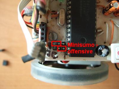
Minisumo defensive program
When executing this program, the minisumo robot has to detect the opponent and push it out of the ring. More, MR1 has to take care not to go outside of the ring by its own. The feature that makes the difference between this program and the minisumo offensive program is that MR1 performs a "slip away" manoeuvre immediately after the first 5 seconds elapsed. The goal is to avoid a very quick robot that could attack directly and immediately after the first 5 seconds.
The next picture shows states in which the robot is when executes this program:
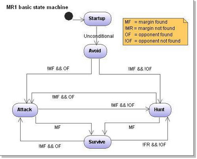
Minisumo defensive program
It’s almost the same as the minisumo defensive program, the only difference is that the slip away manoeuvre is not executed at all.
Line follower program
When executng
this program, MR1 has to follow the path created by a black line on a white
floor. The width of the line must be at least 1.5 cm. MR1
is a minisumo robot, line following functionality not being important, I don’t
insist on this program ( and I didn’t when I wrote the software).